Overview
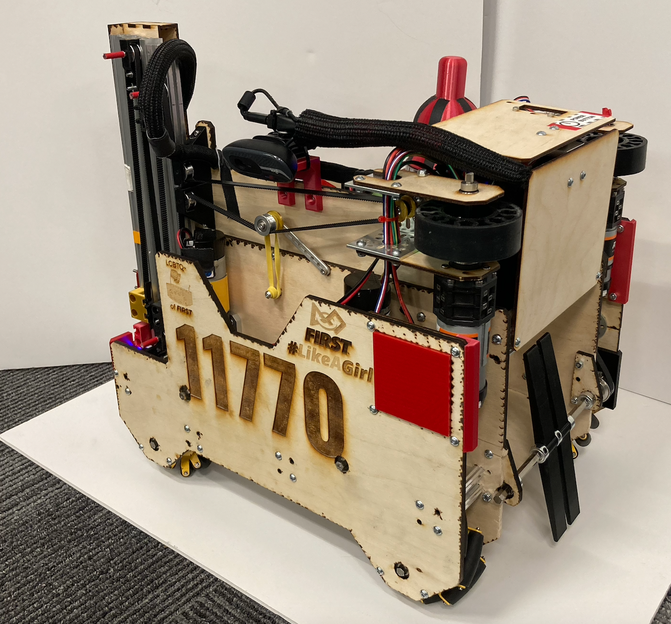
For six years, I was part of my high school's FIRST Tech Challenge Team, Curiosity 11770. As a founding member of the team, I gained invaluable experience leading engineering projects and designing a complex system. I served as the team's computer-aided design (CAD) lead from 2019 to 2022 and as captain from 2020 to 2022. FIRST Tech Challenge was my first real exposure to the engineering design process, and I've loved robotics ever since! Check out Curiosity's Website for more details.
2021-2022 Season
Engineering Portfolio
Part of the competition required the submission of an engineering portfolio. I led the creation, organization, and refinement of this document. As a team captain, I ensured that each member contributed to the portfolio and that the portfolio showcased our journey as a team. We placed first in the award for the portfolio in both competitions we attended. Some sample pages are shown below.
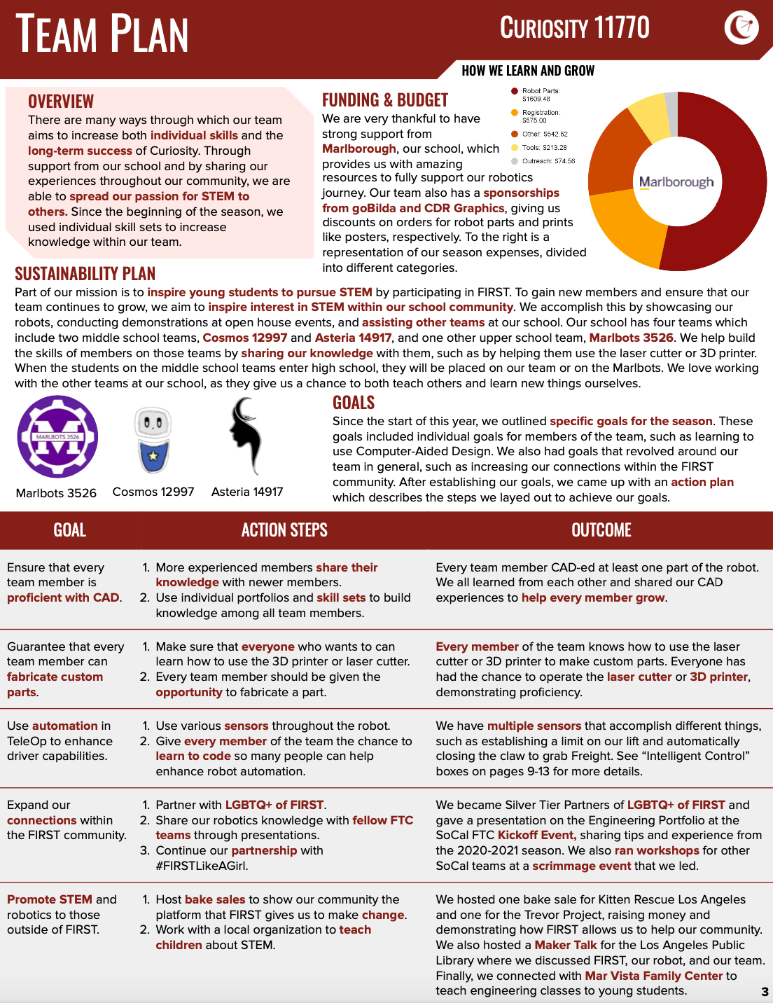
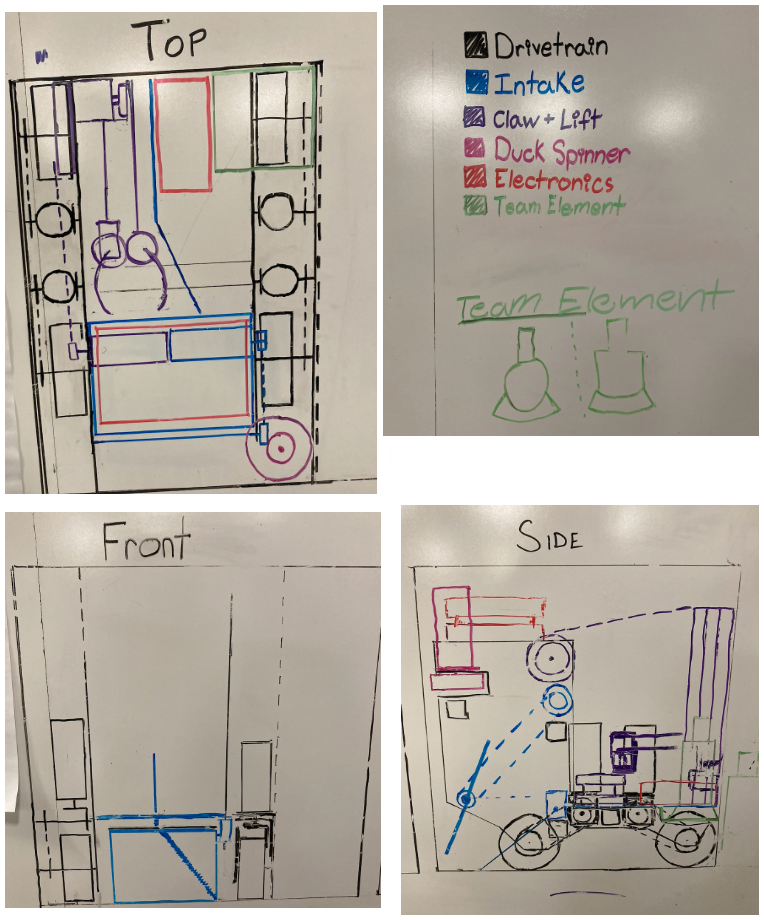
The "Team Plan" page which shows our goals for the season and beyond.
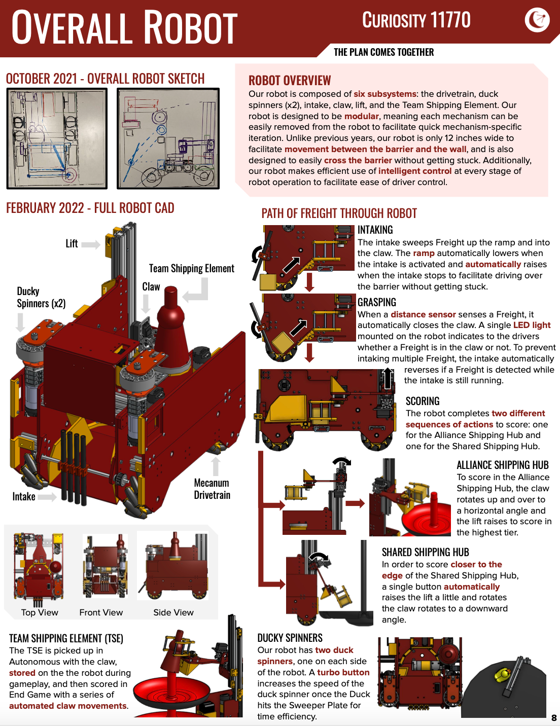
The "Overall Robot" page illustrates how the robot moves and operates.
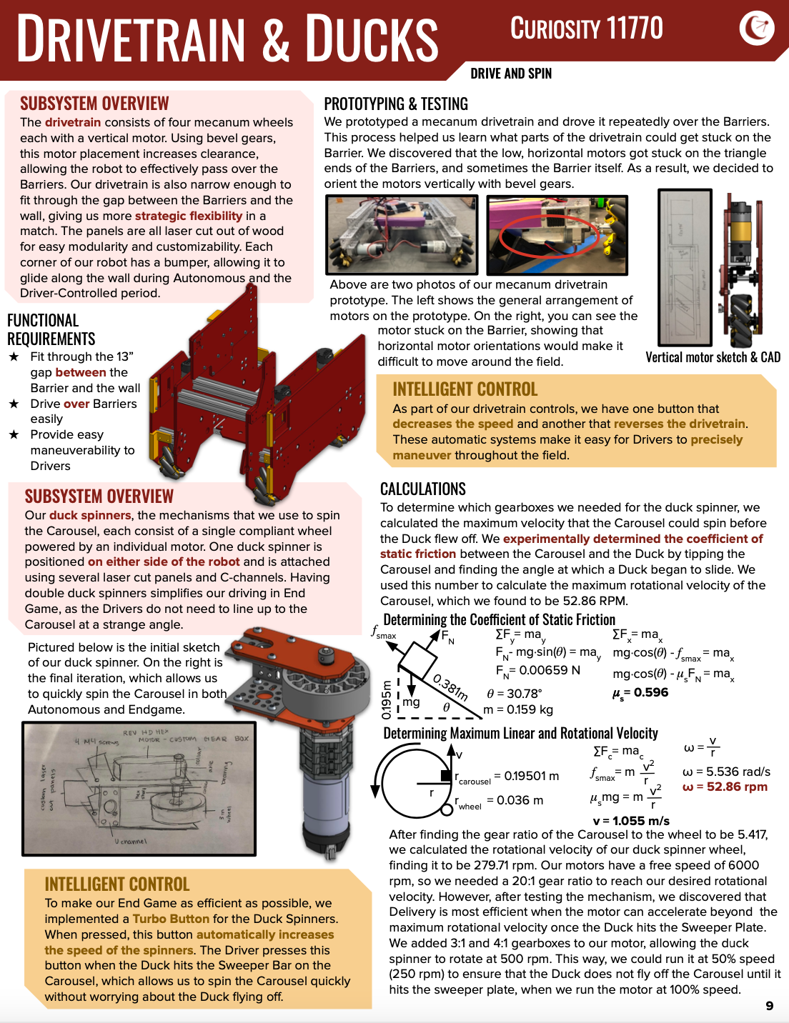
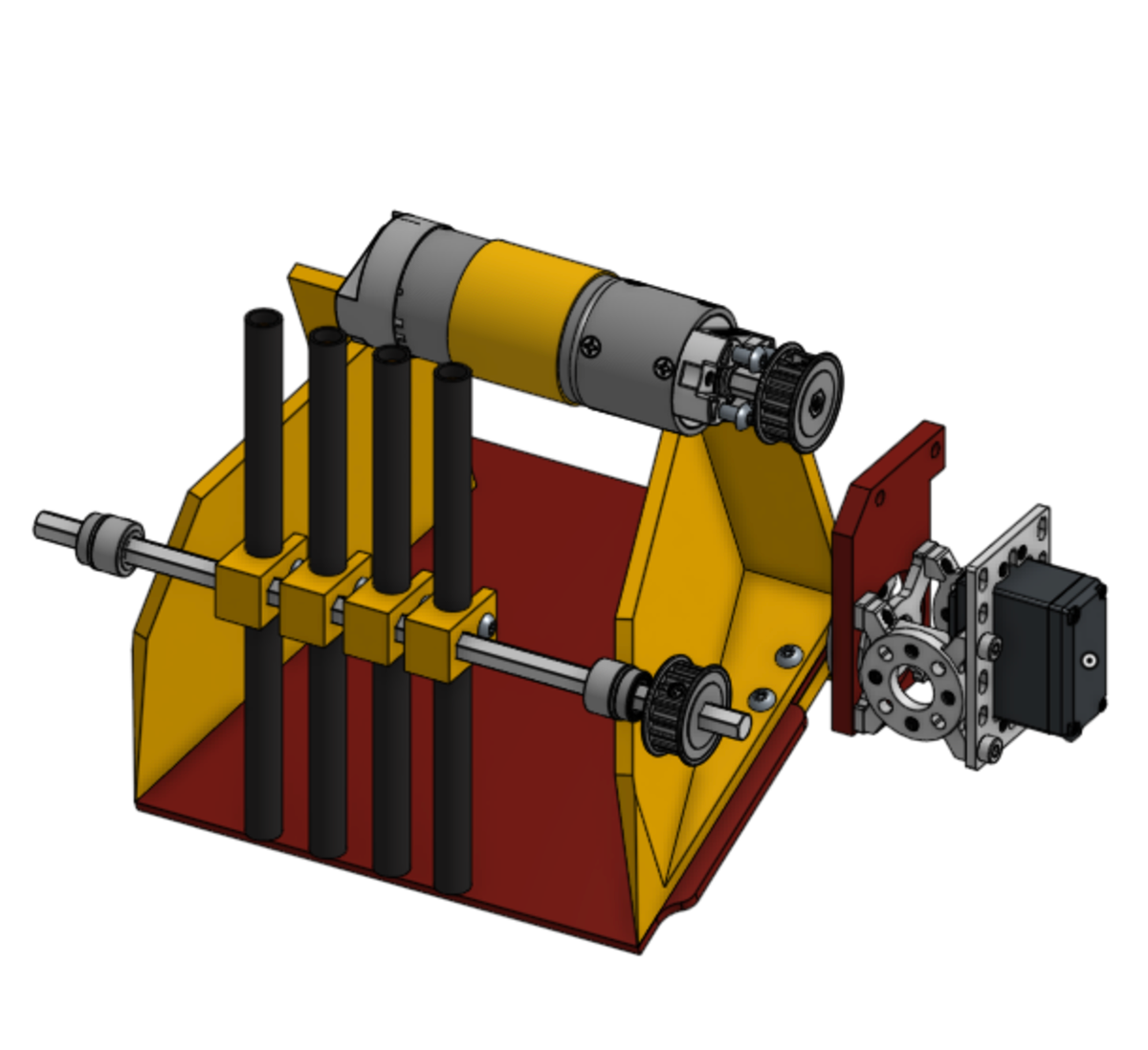
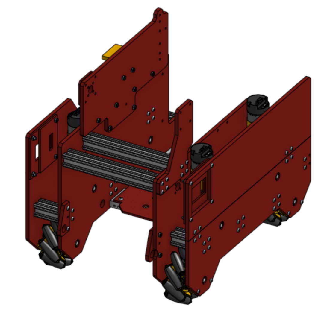
The "Drivetrain and Ducks" page shows the details of two of our robot's mechanisms: the drivetrain and the "duck spinners" which were used for a specific task in the game.
Computer Aided Design
As the team's CAD lead from 2019-2022, I had the opportunity to help many of my teammates learn to use OnShape. I also CAD-ed a lot of parts in OnShape: I created custom panels that we laser cut for the robot, various parts to 3D-print, assemblies to understand how the overall robot would fit together, and part drawings for documentation. Below are CAD screenshots and drawings.
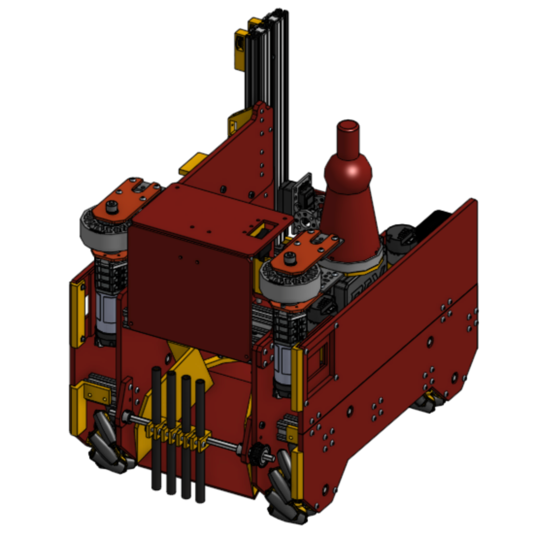
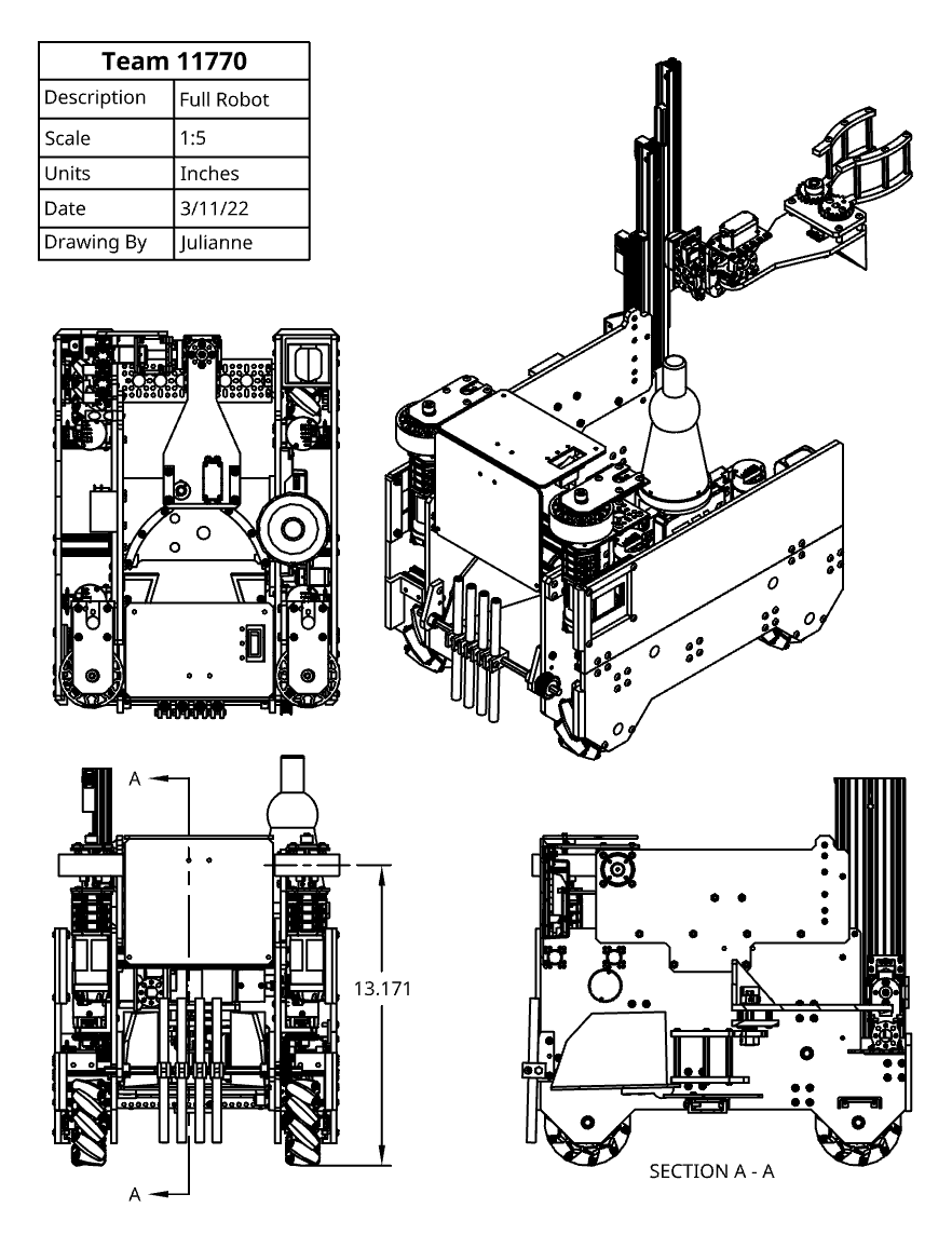
The above pictures and screenshots show the progression of our robot from early sketches to final CAD. On the left is a multi-view sketch that I created. On the right is the final CAD drawing of our overall robot.
Assembly
After CAD-ing our robot, we laser cut and 3D print parts and put the robot together. These manufacturing tools allowed us to quickly and efficiently iterate the robot.
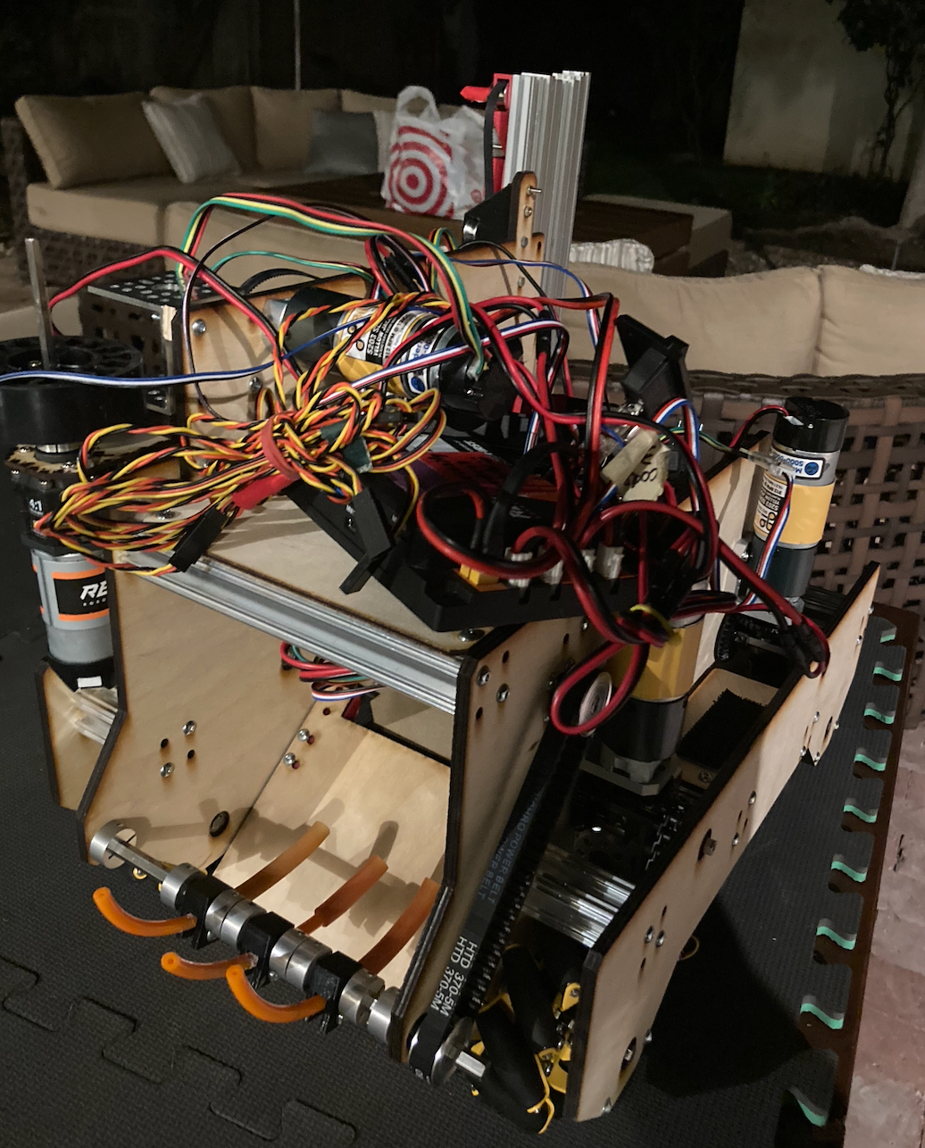
An early assembly of our robot. As you can see, the intake is made of a completely different material than it is in the final robot.
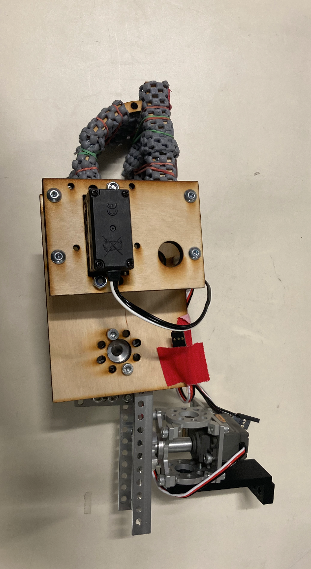
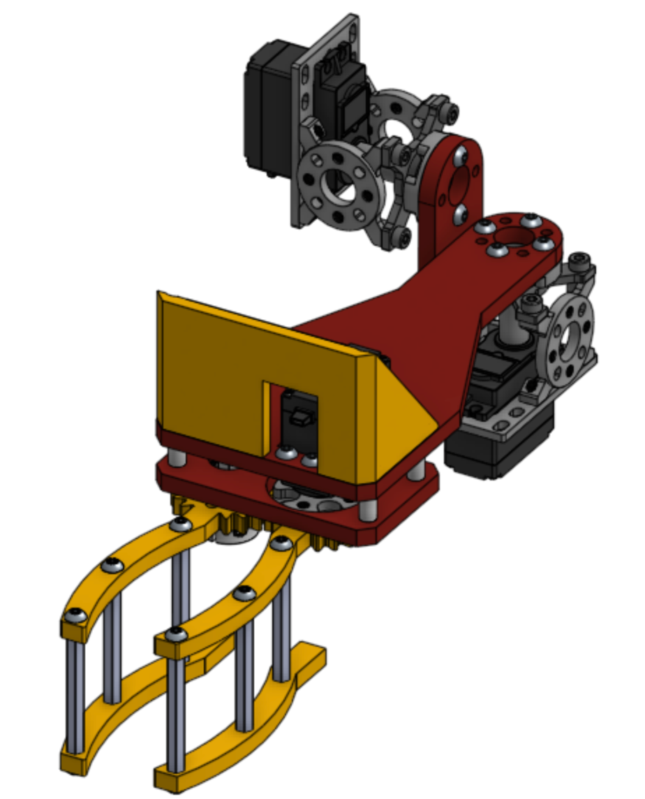
This is an early version of our claw, which is much boxier and less adaptable than our final claw.
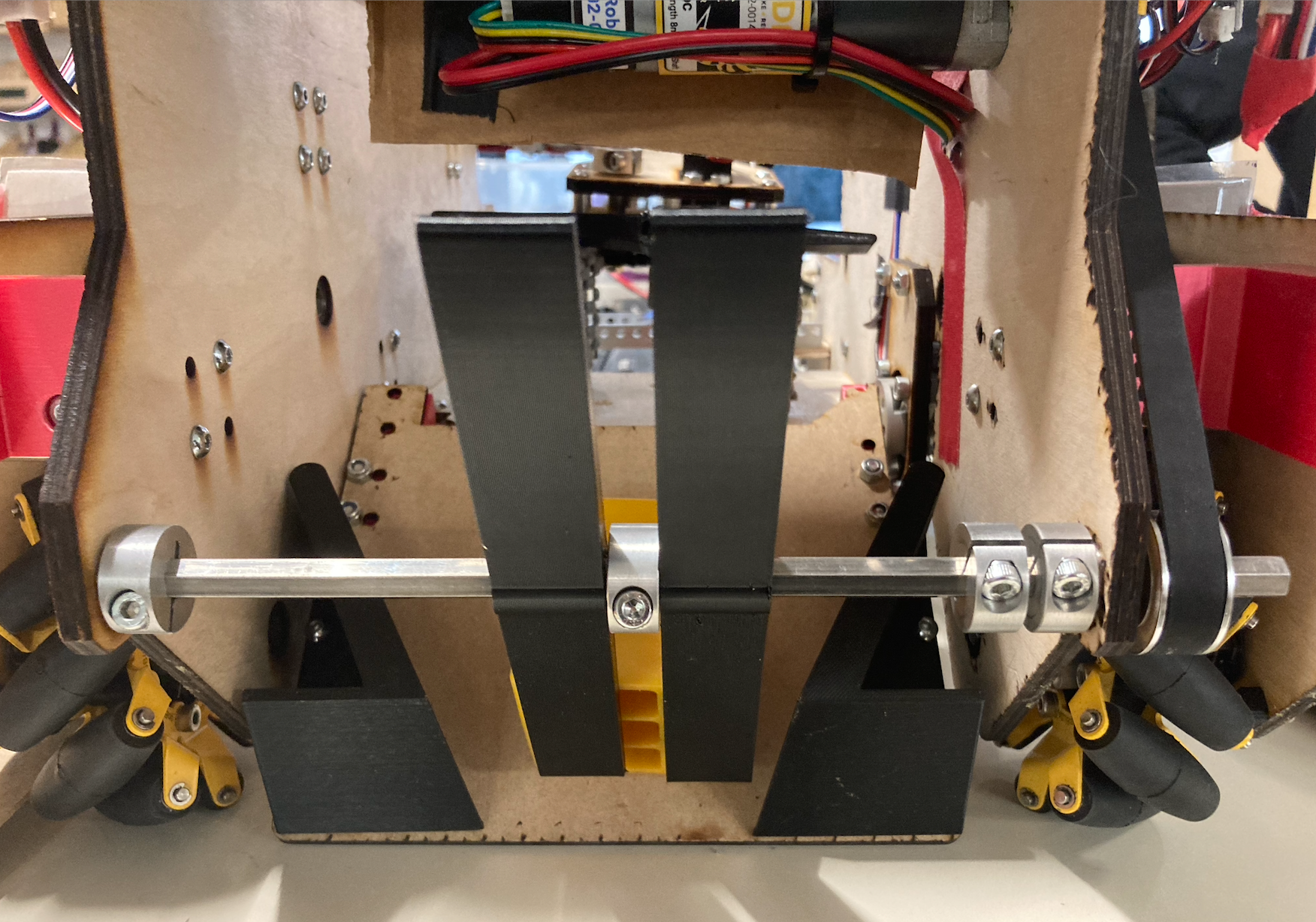
This picture shows the final version of our intake, made out of 3D-printed TPU flippers (TPU is a flexible material).
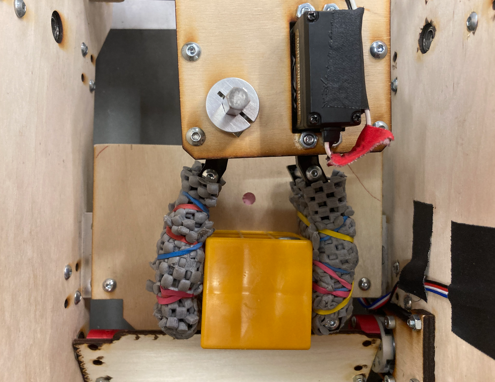
A later claw iteration. Unlike the first iteration, this claw has two mobile sides, making it easier to grasp both a ball and block.